
Effect of Internal Hex Height and Collar Height on Marginal Fit of Implant Abutment Connection after Dynamic Cyclic Loading: (In Vitro Study)
Research
Published on: 2021 01 26
By: Mennat-Elrahman Elsayed , Eman Shakal , Tamer Mostafa
Abstract
Limited comparative data are available regarding the effect of internal hex height and abutment collar height on screw loosening and microgap formation. Eighty stock straight abutments with different internal hex height and collar height were divided into four equal groups (N=20): twenty each according to height of hex and collar height of abutment itself. Group I: abutment with.1 mm hexagon height and 1mm collar height, group II: abutment with 0.6 mm hexagon height and 1mm collar height, group III: abutment with 0.6mm hexagon height and 3mm collar height, group IV: abutment with 0.6mm internal hexagon height and 4mm collar height. Each fixture was vertically placed in the center of the epoxy resin block using a modified dental surveyor. Metal tubes were fabricated to fit accurately on abutments. The samples were subjected to eccentric cyclic loading at three different intervals 10000, 100000,500000 cycles. Marginal fit was evaluated before and after each cycle by measuring microgap size in (μm) using scanning electron microscope with a magnification 700x. The values of microgap size in μm before and after cyclic loading were analyzed using paired t-Student tests one way ANOVA followed by Tukey’s post-Hoc test.
Statistical significance differences were found between all study groups with the highest value recorded to Group IV abutments (20.966±2.795) while minimum value recorded to Group I abutments (8.400±2.166). Increasing the internal hexagon height and decreasing the collar height leads to increase the marginal fit of implant abutment connection.
Introduction
On the impact of internal hex height and abutment collar height on screw loosening and microgap formation, there seems to be limited comparative evidence. Mechanical complications of dental implants are not only due to biological factors, such as osseointegration or the presence of periimplantitis, but also results from mechanical complications such as implant body-fixture fracture, fracture prosthesis with the most frequent observed complication of screwed and cemented prosthesis is screw loosening leading to microgap formation and misfit of the implant abutment interface (1).
Abutment screw loosening is caused by a number of factors, including the screw itself, connection type, screw diameter, platform diameter, surface condition, vibrating micro movement, microleakage, abutment diameter, dynamic fatigue, abutment angulations, lateral cyclic loading, insufficient tightening torque and retorque, settling impact, collar length, and more. (2-15)
For any lateral load applied to the abutment screw in external hexagon structures, the hex height was directly proportional to the stress applied to the abutment screw. The external hexagon attachment has been shown to be inadequate as an anti-rotation device and to be unable to withstand intraoral forces. (16)
Internal hex implant-abutment connections were created to address the clinical issues that occur with external hex connections. They also have a better chance of achieving a microbial seal between the abutment and implant than external connections. (16) It has the drawback of having a thin lateral fixture wall that can be breached by strong lateral forces. (16)
Although several studies have looked into screw loosening, there is a deficiency of comparative evidence on the impact of different abutment collar heights on screw loosening and microgap forming.
Materials and methods
For this in-vitro analysis, Eighty stock straight abutments with different internal hex heights and collar heights were chosen and divided into four equivalent sections, each with twenty abutments:
- Group I: abutment with 1 mm internal hexagon height and 1mm collar height
- Group II: abutment with 0.6 mm internal hexagon height and 1mm collar height
- Group III: abutment with 0.6mm internal hexagon height and 3mm collar height
- Group IV: abutment with 0.6mm internal hexagon height and 4mm collar height
Specimen preparation:
Eighty blocks were fabricated from epoxy resin material (Solvent free transparent epoxy, KEMAPOXY 150), mixed according to manufacturer’s recommendation and poured in specific stainless mold with a special indicator to determine the point of implant site. After complete setting of epoxy resin blocks all implant fixtures with a length of 10 mm and diameter 4.25 mm (Roott Dental Implant System company, Switzerland) were inserted vertically in the center of epoxy resin block using modified dental surveyor until the implant platform situated approximately 1mm above the resin level.
Abutment preparation:
Different internal hex heights and collar heights of implant abutments were secured to their corresponding fixtures. The abutment screw was initially tightened with a digital torque gauge at 15 N/cm. After tightening; two locations were marked on the upper aspect of abutment and implant neck till the top part of the fixture as one line using carbide fissure bur.
Identical resin patterns of each group were milled by the milling machine (Roland, WI, USA) and fabricated to fit accurately on abutments with an opening on top part wide enough to facilitate tightening and removal of abutment screw. The desired design and dimensions of metal tube was achieved by using 3D software, (Dentcrate, Exocad) with flat occlusal surface parallel to the horizontal plane and 10 mm in width.
The abutment patterns were cast using a lost wax technique. Sprues were glued to wax patterns and phosphate-bonded investments were applied; later, the wax was burned away and molten metal was cast into the mold formed by the wax pattern. The casting was divested of aluminum oxide air abrasives, cleaned, and then tested after the investment was broken down.
Water balance device is adjusted over the top of the metal to ensure 180-degree surface and parallel to the floor before cementation to the corresponding abutment, this procedure is repeated.
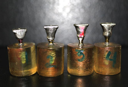
After forgery of the metal tube, abutments were cleaned with ethyl alcohol then secured to their fixtures.To shield the top portion of the fixture that protruded above the epoxy resin block during cementation, Teflon was added. For defense and preservation of the screw, cotton roll and flowable composite resin were adapted above the access of screw holes of each abutment. Metal tubes were covered with a very thin film of separation medium (Vaseline) and left for ten minutes before being coated with glass ionomer type II cement (GIC Fuji Gold Label type II, Japan) using a bond brush. A gentle baby brush was used to clear any excess cement. (fig-1)
Application of cyclic loading
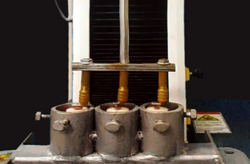
Samples were inserted in a custom jig and mounted in the lower fixed compartment of the computer controlled universal testing machine. Dynamic cyclic load of the 133 N was applied eccentrically away from the center of abutment using a metallic rod with round tip, which was connected to the upper movable compartment of the machine. A target of 500,000 cycles was defined and this load was applied at three intervals of 10000, 100000, 500000. (fig 2.)
Measurement of micro gap at implant/ abutment interface:
Following the cycling load, each assembly was immersed in warm water to facilitate the separation of the metal tube from the abutment, and then washed with ethyl alcohol in an ultrasonic cleaning bath for five minutes to clear any traces from the implant surface before screening. To render samples conductive, each asset was plated with a thin layer of gold for around three minutes.
Before and after each cyclic filling, the micro gap size at five positions at the implant abutment interface was measured using an electron microscope. Measurements were taken, and the t-Student scale was used to do statistical research.
Results
It was noticed that the microgap measurements of the four groups increased significantly after different loading cycles. The difference between four abutments with different internal hexagon height and collar height was statistically significant.
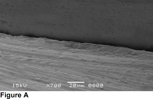
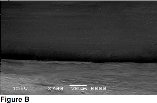
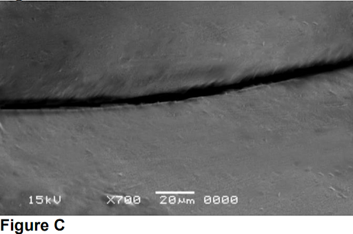
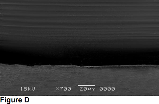
Figure 4 A-D. Scanning electron photographs of microgap formation for the four groups after 500000 cycles dynamic cyclic loading.
Discussion
The purpose of this analysis was to see how internal hex height and collar height affected implant abutment marginal fit before and after complex cyclic loading. It was recommended that hex height should be a minimum of 1.2 mm to provide both lateral and rotational stability (17).
Each specimen was subjected to dynamic cyclic loading using universal testing machine with 133 N cyclic and frequency of 1 HZ was applied to simulate values in human mastication.(18) Dynamic cyclic loading used to simulate masticatory function mimic oral cavity that might lead to a biological and mechanical complication of implant abutment connection. Also, it is a reliable method to test the effect of mechanical fatigue on the implant abutment joint stability.(19)
The higher the abutment collar height after dynamic cyclic loading, the more microgaps develop at the implant abutment attachment, according to the findings of this research. This discovery is consistent with previous research by Siadat et al.(14) and El-Sheikh et al., (20) who found that the abutment collar length serves as a vertical cantilever that magnifies energy.
The current in vitro research found that raising the cyclic loading up to 500000 cycles increased the size of the microgap variable at the implant abutment interface, which may be clarified by the back off principle. The abutment screw is defined by Cibirka and colleagues (21) as a spring that is stretched by preload and kept in place by the frictional fit of threads. External forces can cause threads to back off, resulting in a reduction in successful preload and a reduction in the screw’s ability to sustain joint integrity, resulting in an increase in the implant-abutment interface gap space.
Long internal hex of abutments has the least microgap forming and more marginal fit at implant abutment interface in the current analysis. This can be clarified by the length of the implant–abutment joint, which may be a cause for the variations in bacterial penetration, with internal conical contacts having a significantly lower degree of bacterial leakage. (22-24)
Conclusion
It is concluded that increasing the abutment internal hexagon height and decreasing collar height will lead to decreased microgap formation between implant and abutment.
Clinical significance
Using implant systems with abutments having long internal hexagon and short collar height (if it is clinically suitable) will increase the marginal fit of implant abutment connection.
References
- Barbosa GA, Bernardes SR, Neves FD, Fernandes Neto AJ, Mattos MD, Ribeiro RF. Relation between implant/abutment vertical misfit and torque loss of abutment screws. Braz Dent J: 2008; 19(4):358-63
- Misch CE. Principles for Abutment and Prosthetic Screws and Screw-Retained Components and Prostheses. Dental Implant Prosthetics: Elsevier; 2015. 724-52
- Attiah E, Elgendy A, Mostafa TM. Effect of dynamic cyclic loading on screw loosening of retightened versus new abutment screw in both narrow and standard implants (in-vitro study). Int J Implant Dent: 2020;28;6(1):30.
- Sahin C, Ayyildiz S. Correlation between microleakage and screw loosening at implant-abutment connection. J Adv Prosthodont: 2014(1);6:35-8.
- Michalakis KX, Calvani P, Muftu S, Pissiotis A, Hirayama H. The Effect of Different Implant-Abutment Connections on Screw Joint Stability. J Oral Implantol: 2014;40(2):146-52.
- Cho S-C, Small P-N, Elian N, Tarnow D. Screw Loosening for Standard and Wide Diameter Implants in Partially Edentulous Cases: 3- to 7-Year longitudinal Data. Implant Dent: 2004;13(3):245-50.
- Karaman T, Kahraman O. Comparison of Reverse Torque in Different Types of Implant Screw Systems. J Int Dent Med Res 2020; 13(1): 101-5
- Kim SG, Chung CH, Son MK. Effect of cement washout on loosening of abutment screws andvice versain screw- and cementretained implant-supported dental prosthesis. J Adv Prosthodont: 2015;7(3):207-13
- Xia D, Lin H, Yuan S, Bai W, Zheng G. Dynamic fatigue performance of implant-abutment assemblies with different tightening torque values. Bio-Medical Materials and Engineering: 2014; 24(6):2143-9.
- Cavallaro J, Greenstein G. Angled Implant Abutments. JADA: 2011; 142(2):150-8.
- Khraisat A, Abu-Hammad O, Dar-Odeh N, Al-Kayed AM. Abutment Screw Loosening and Bending Resistance of External Hexagon Implant System after Lateral Cyclic Loading. Clin Implant Dent Relat Res: 2004; 6(3) :157-64.
- Khraisat A, Hashimoto A, Nomura S, Miyakawa O. Effect of lateral cyclic loading on abutment screw loosening of an external hexagon implant system. J Prosthet Dent: 2004;91(4):326-34.
- Winkler S, Ring K, Ring JD, Boberick KG. Implant Screw Mechanics and the Settling Effect: An Overview. J Oral Implantol: 2003;29(5):242-5.
- Siadat H, Pirmoazen S, Beyabanaki E, Alikhasi M. Does Abutment Collar Length Affect Abutment Screw Loosening After Cyclic Loading? J Oral Implantol: 2015;41(spec):346-51.
- Steinebrunner L, Wolfart S, Bößmann K, Kern M. In vitro evaluation of bacterial leakage along the implant-abutment interface of different implant systems. Int J Oral Maxillofac Implants: 2005;20(6):875-81.
- Tsuge T, Hagiwara Y. Influence of lateral-oblique cyclic loading on abutment screw loosening of interna
- Shetty M, Shetty NH, Jaiman R. Implant abutment connection: Biomechanical perspectives. Nitte Univ J of Health Sci: 2014;4:47- 53.
- Jemt T, Karlsson S, Hedegard B. Mandibular movements of young adults recorded by intraorally placed light-emitting diodes. J Prosthet Dent: 1979;42(6):669-73
- Kim E-S, Shin S-Y. Influence of the implant abutment types and the dynamic loading on initial screw loosening. J Adv Prosthodont: 2013;5(1):21-9.
- El-Sheikh MAY, Mostafa TMN, El-Sheikh MM. Effect of different angulations and collar lengths of conical hybrid implant abutment on screw loosening after dynamic cyclic loading. Int J Implant Dent: 2018;4(1):1-12.
- Cibirka RM, Nelson SK, Lang BR, Rueggeberg FA. Examination of the implant—abutment interface after fatigue testing. J Prosthet Dent: 2001;85:268-275.
- Assenza B, Tripodi D, Scarano A, Perrotti V, Piattelli A, Iezzi G, D’Ercole S. Bacterial Leakage in Implants With Different Implant– Abutment Connections: An In Vitro Study. J Periodontal Res: 2012;83(4):491-7
- Tripodi D, Vantaggiato G, Scarano A, Perrotti V, Piattelli A, Iezzi G, et al. An In Vitro Investigation Concerning the Bacterial Leakage at Implants With Internal Hexagon and Morse Taper ImplantAbutment Connections. Implant Dent: 2012;21(4):335-9
- Dias E, Sperandio M, Napimoga M. Association Between Implant-Abutment Microgap and Implant Circularity to Bacterial Leakage: An In Vitro Study Using Tapered Connection Implants. Int J Oral Maxillofac Implants: 2018;33(3):505-11.
Full research:
http://www.jidmr.com/journal/wp-content/uploads/2021/03/13-E-D20_1270_Tamer_Mostafa_Egypt.pdf